T.C. Electronics TC XII B/K programmable Phaser
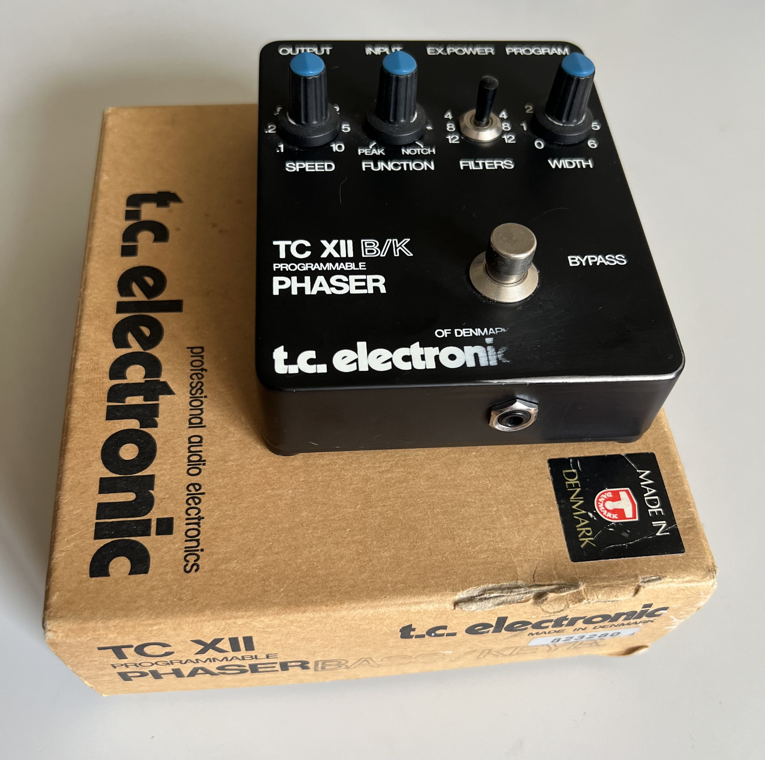
This phaser was built in the early eighties. It was available in a normal version named TC XII for guitar players. The TC XII B/K is the version for Bass and Keyboards. The difference are only four doubled resistor values und eight about doubled capacitors values. inside to get a "one octave lower bass range".
The black sturdy metal housing is about 9.5 cm x 12 cm x 3 cm (about 3¾" x 4¾" x 1¼") in width, length and height without knobs. There are three knobs (modulation SPEED, FUNCTION and modulation DEPTH). The FUNCTION pot got PEAK in its ccw position and NOTCH on the cw position. The 12'clock setting is LINEAR. A three position switch named FILTER for the number of phaser poles (4,8 or 12). A little red LED next to Input shows operation. If it is blinking at the speed of modulation, you need to change the battery (screw driver needed). And of cause a foot switch for bypass. In the back there are three 1/4" sockets for OUTPUT, INPUT (also acting as on switch) and a TRS socket named PROGRAMM. More on the later a bit later. There is also a 9V 3.5 mm power socket (tip = positive). On the front is another 3.5 mm socket for an external bypass foot switch.
But what about "programmable"? Well, you may use some special 1/4" TRS jacks at the PROGRAMM socket to change the overall sound. These special jacks had either a 4.7 kΩ resistor from tip to base and 82 kΩ resistor from ring to base (BLUE PROGRAMM PLUG) for a "higher sound character" or a 27 kΩ resistor from tip to base and 68 kΩ resistor from ring to base (RED PROGRAMM PLUG) for a "deeper sound character. These special plugs are often missed on used units. They had the colour markings on their end. But now you know how to build your owns.
If you connect the tip and the base of that PROGRAMM socket to a 50 to 100 Ω variable resistor (you may use a modified foot pedal), you may modulate the phaser yourself or together with the build in modulation.
The PROGRAMM socket also let you connect two units for a real stereo arrangement. The special cable with two TRS jacks and in each jack there is a 15 kΩ resistor from tip to base on each end. You may alternativ use two 50 kΩ or two 5 kΩ resistors to get the "red" or "blue" program plug character while using the stereo configuration of two units. You will have to set the WIDTH on one unit to zero to get the stereo sound right.
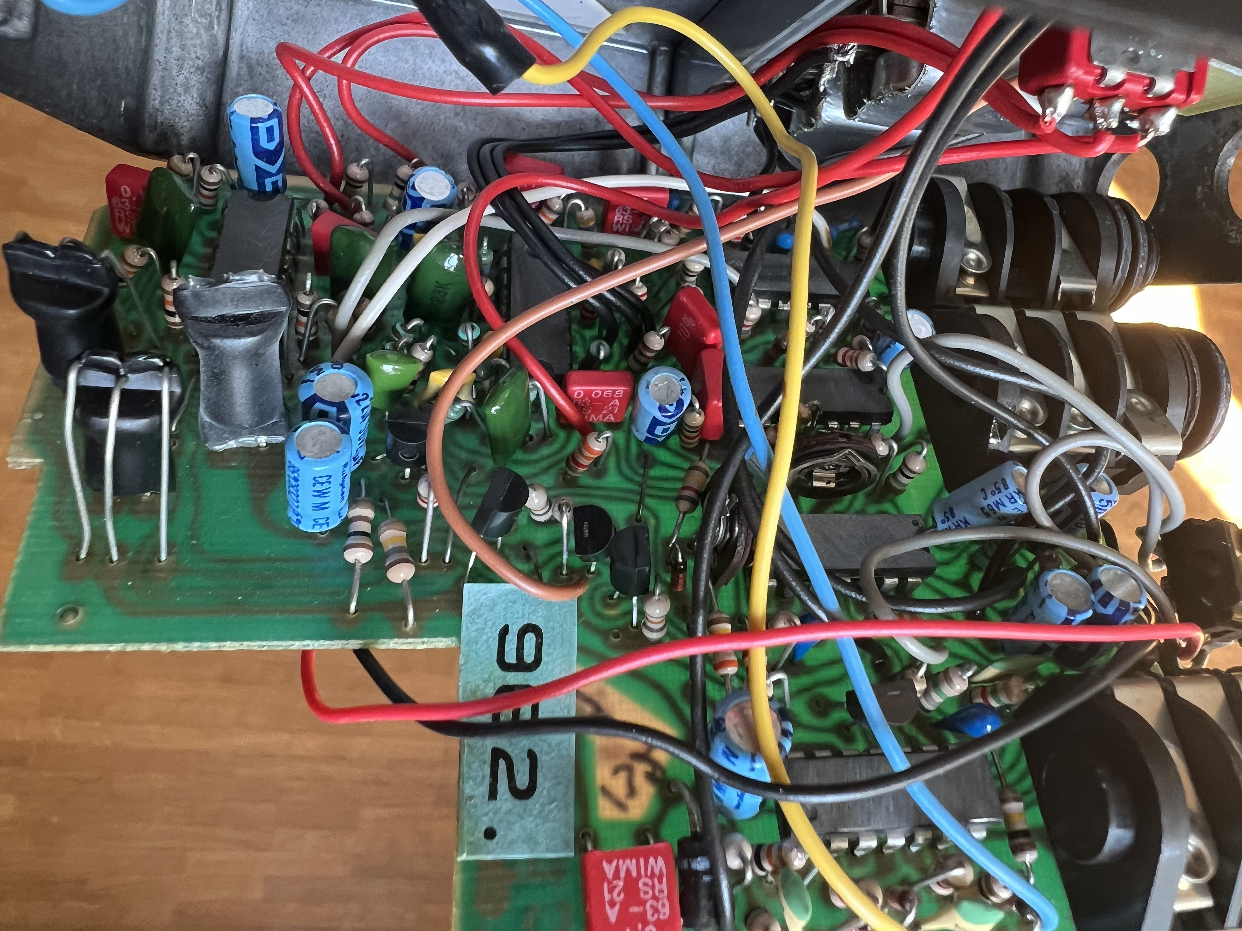
Inside you find 6 sandpapered chips (3 DIP 14 and 3 DIP 16) and to the left three optocouplers (one LED with two photo resistors each).
The sandpapered chips are 3 OP-Amps (XR 4212 and two Raytheon RC 4149), one quad comparator (LM 339), a CD 4011A or UB CMOS Quad 2-Input NAND Gate, and a HEF 4007 UB Dual Complementary Pair Plus Inverter.
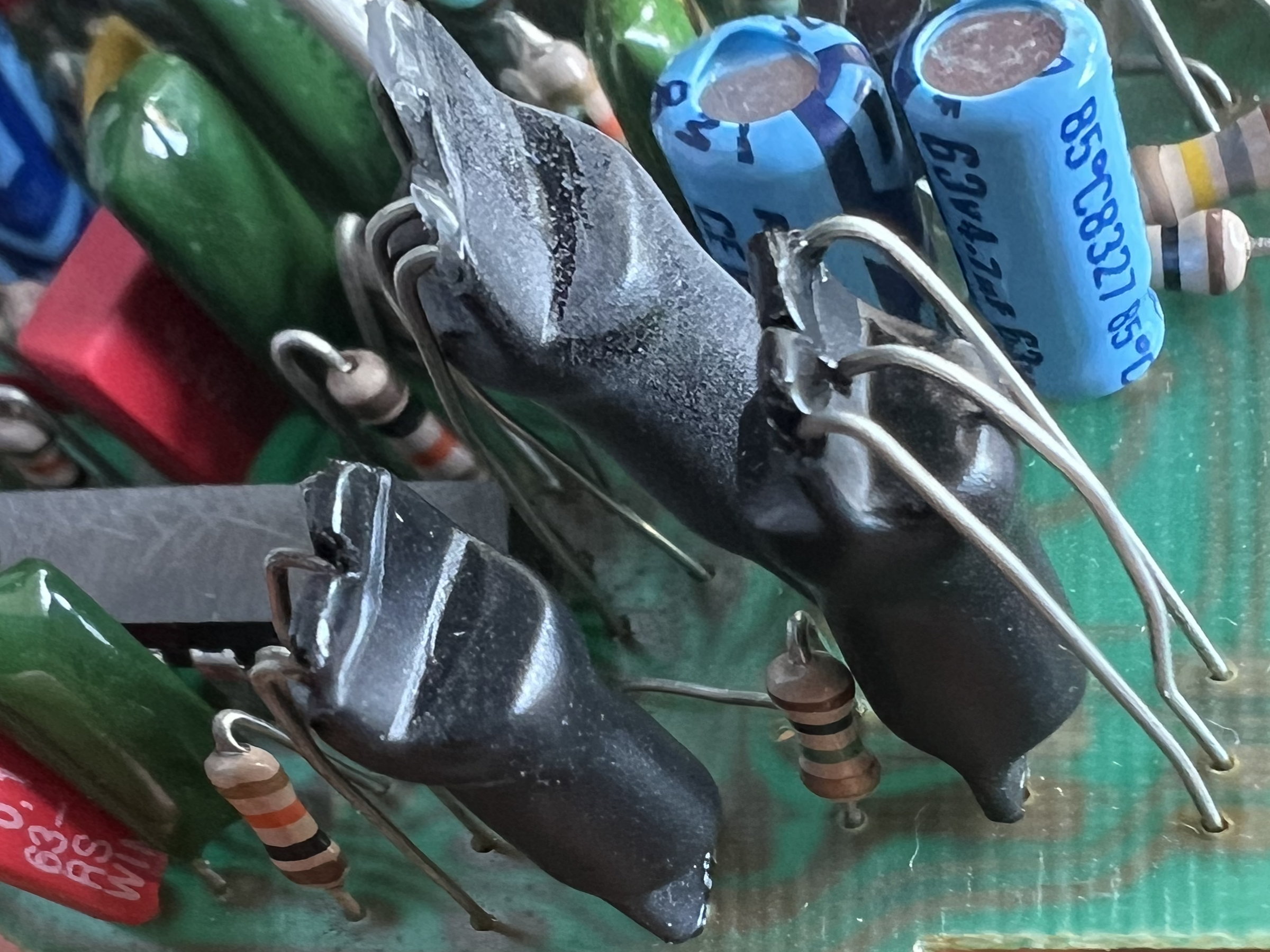
Each optocoupler is made from one LED and two photo resistors. These packages are named "TC OPTO" in the part list. So I guess, TC built these packages from normal parts themself, hence their DIY look.